This article is a bit longer so that the entire bass mechanism can be shown in one piece. There’s no need to worry, though — most of it consists of pictures and videos.
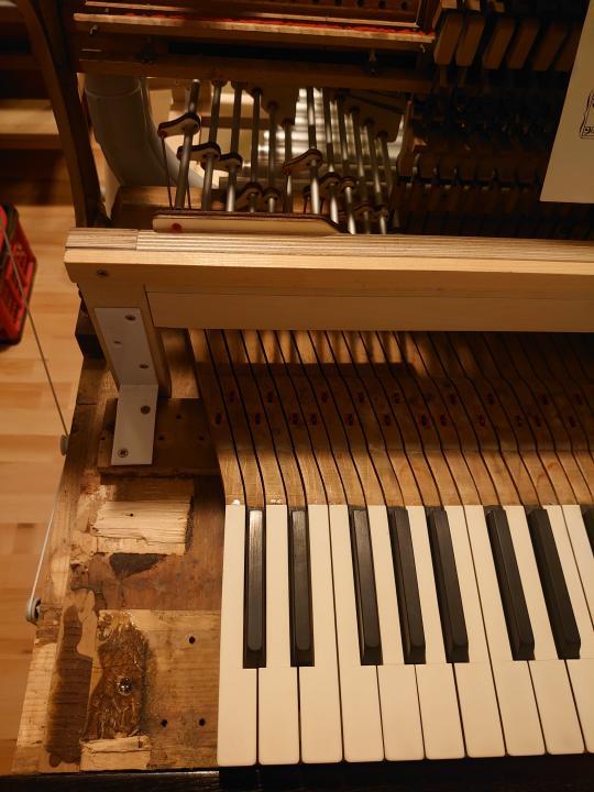
I saved this part for last. For a long time, I wasn’t sure whether to tackle it at all. The bass tones had to be larger to be properly audible, so they no longer fit above the keyboard like the higher octaves. I didn’t know how to connect the keys to the hammers. But when playing certain pieces, I really missed that extra octave. After a long time of thinking and searching for solutions, the right idea finally came to me.
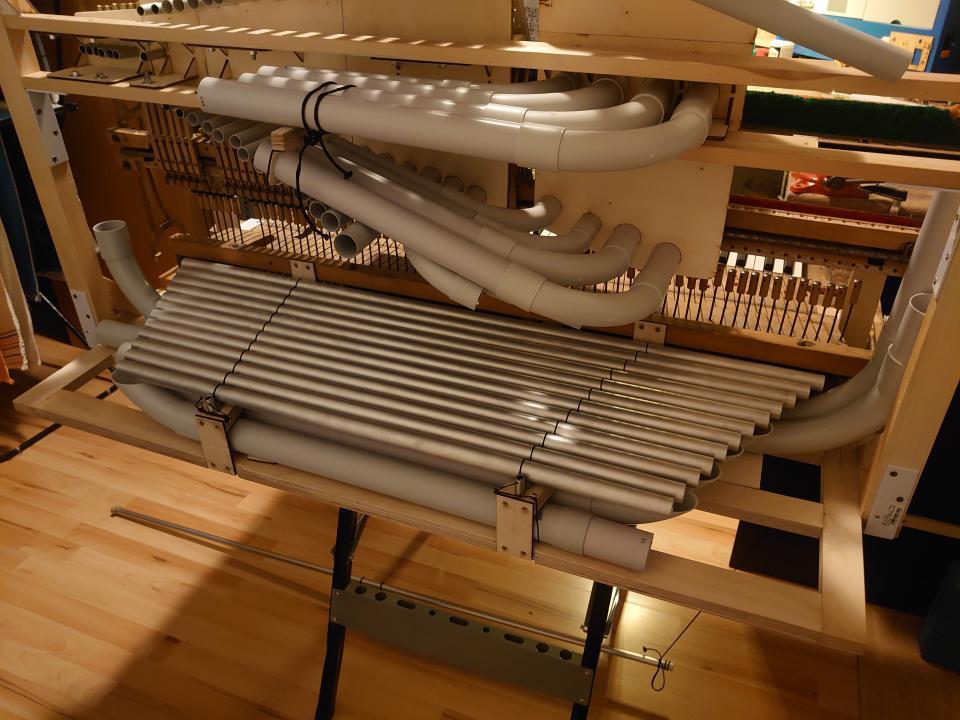
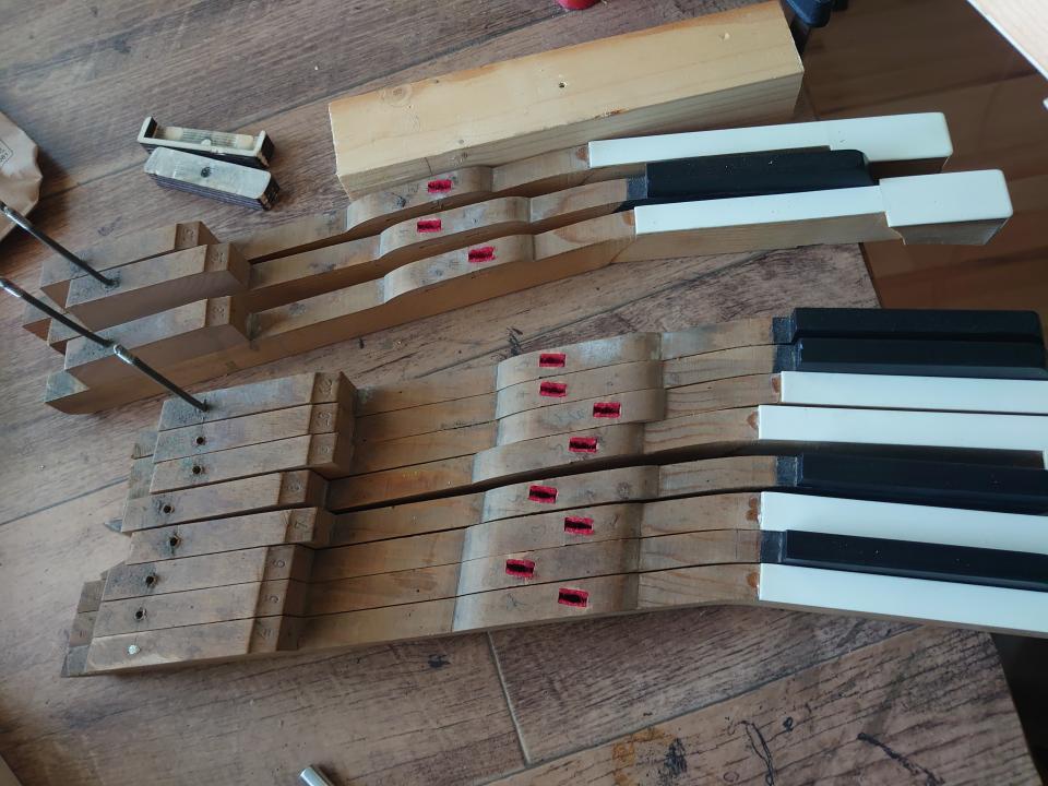
This was my starting point for the bass section mechanism.
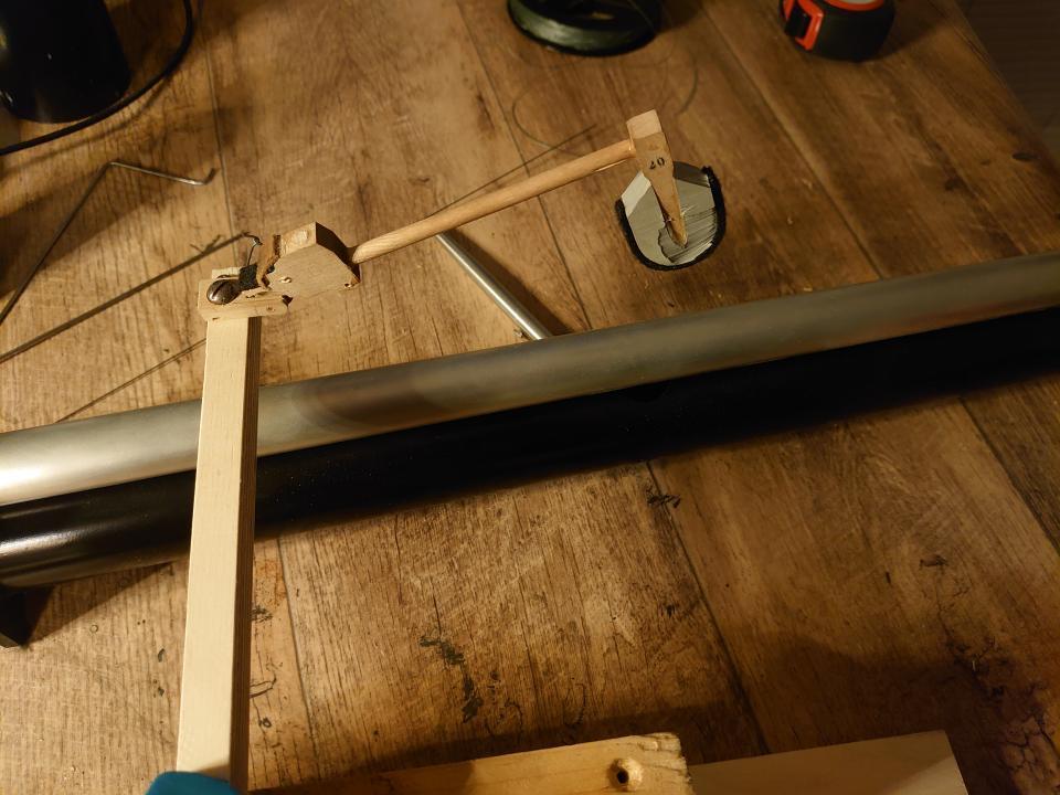
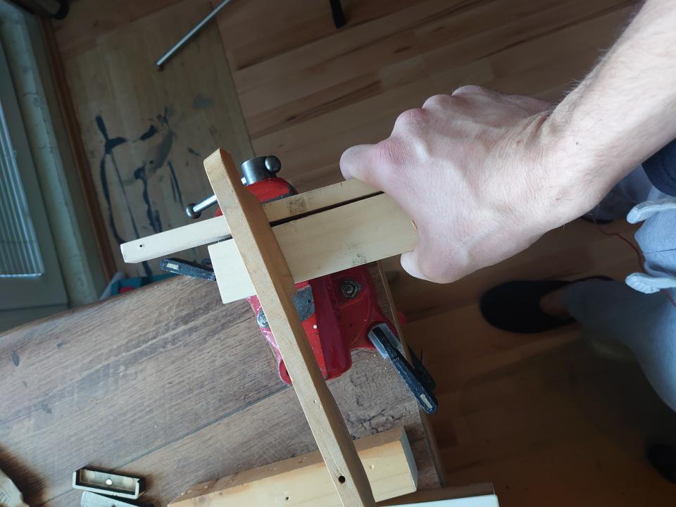
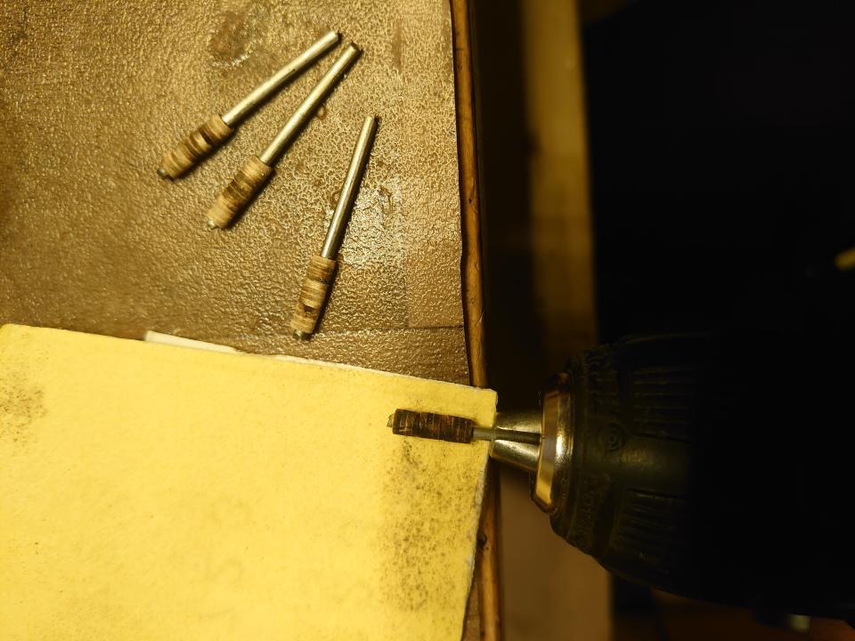
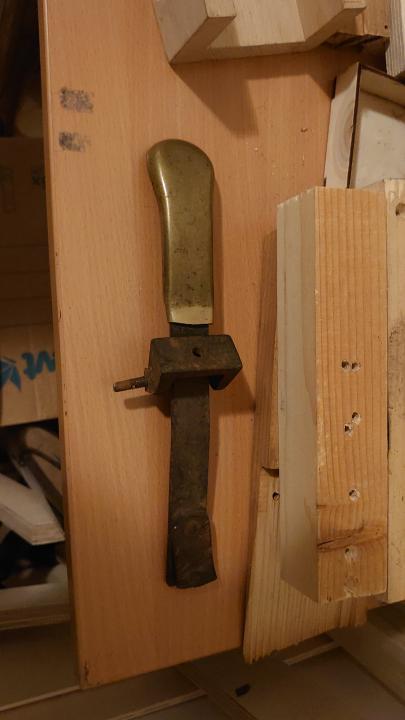
First, I had to make a test hammer to find out how it would sound.
So I covered the hammer with rubber and felt and started testing.
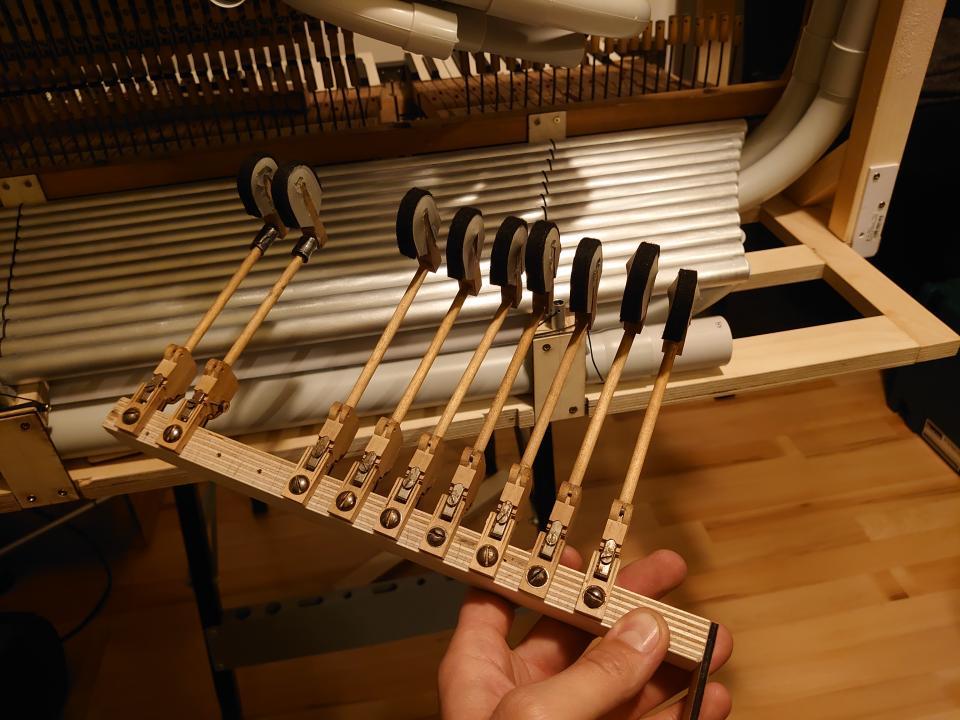
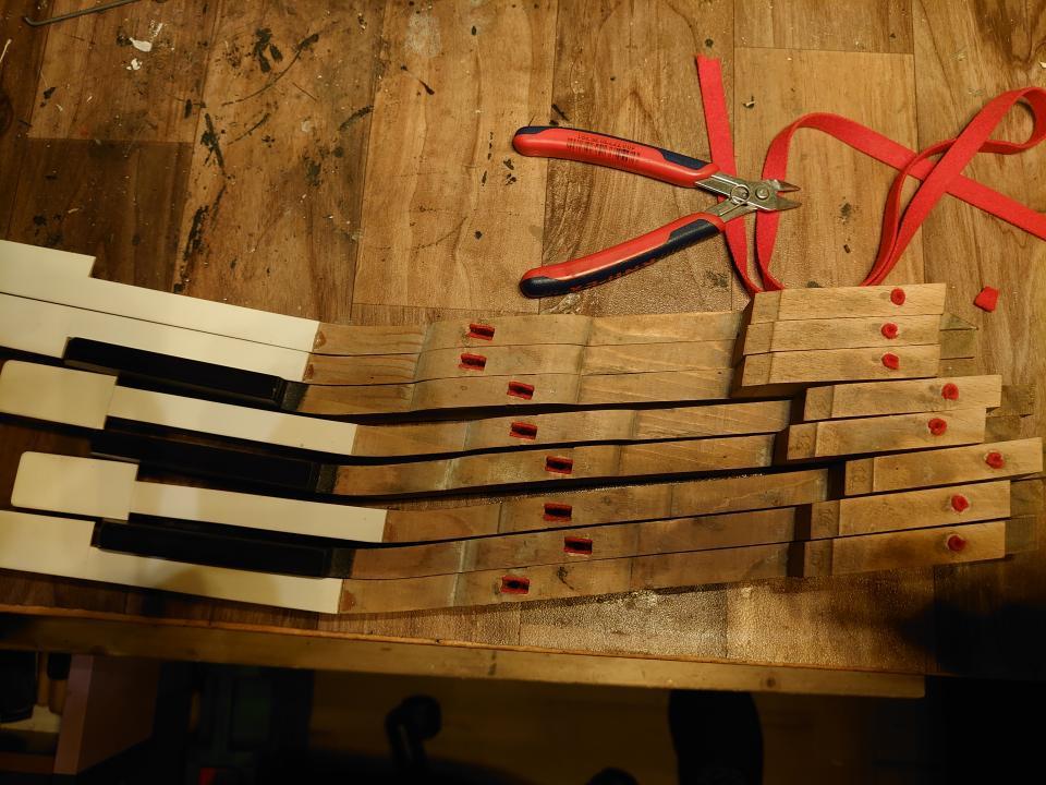
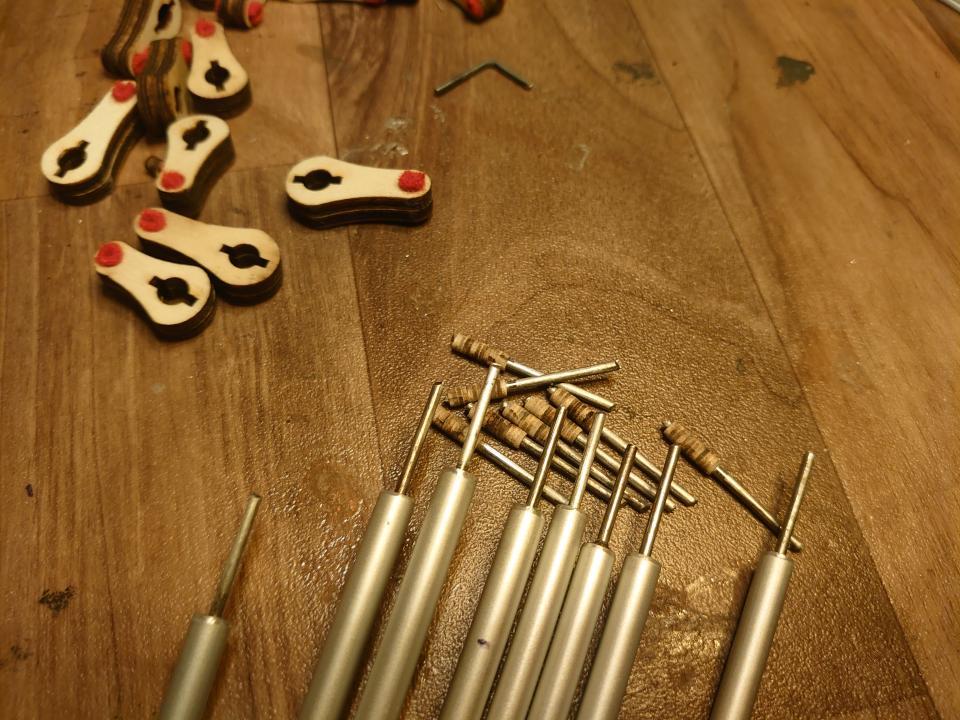
When I was satisfied with the result, I could replicate it for the whole octave — 12 notes.
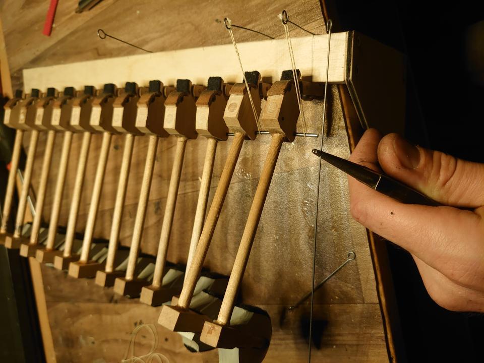
Mounted hammers on the support plate.
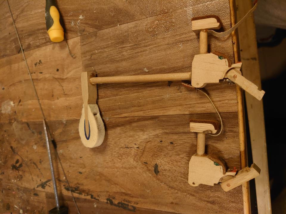
At this stage, I still had enough mechanical parts from the original piano, so I could use them. Another necessary component was the dampers. I made them from the original hammers, using their joints.
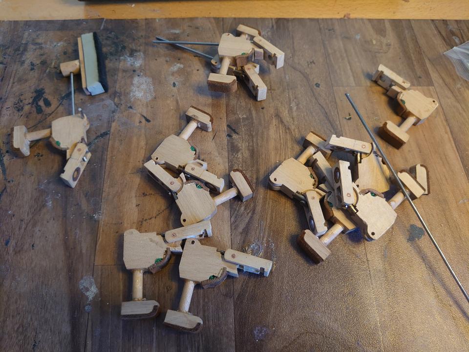
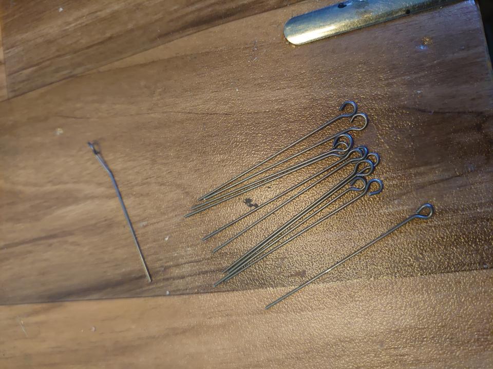
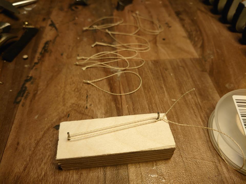
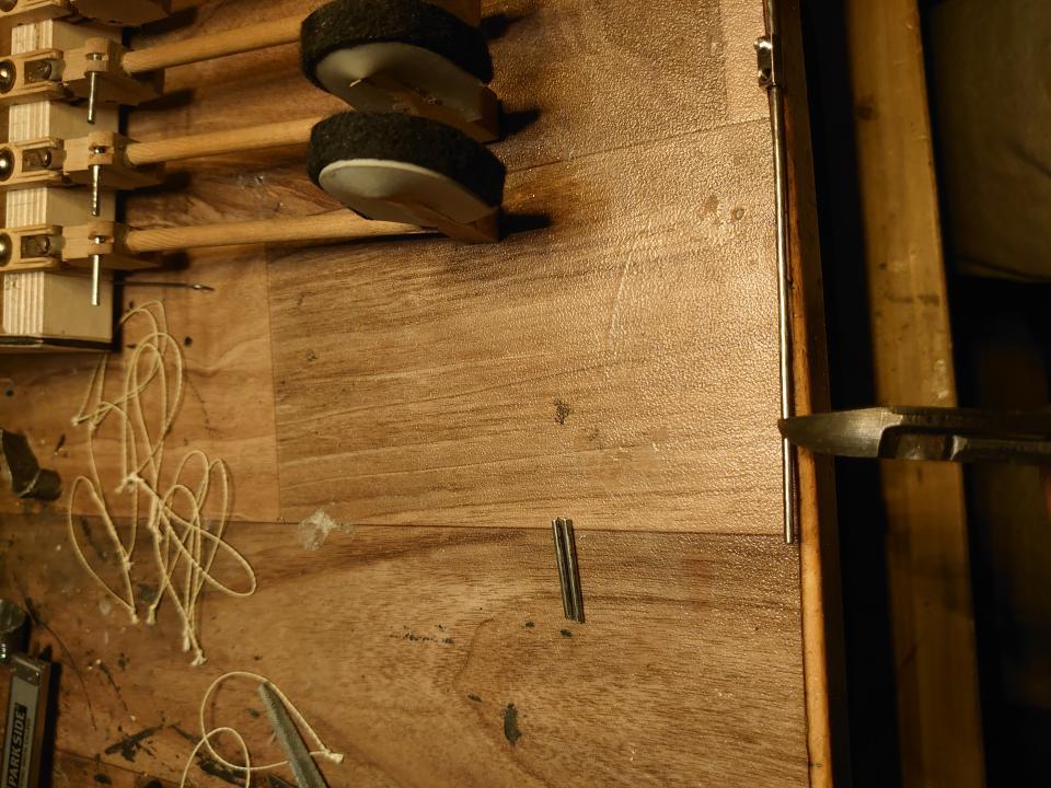
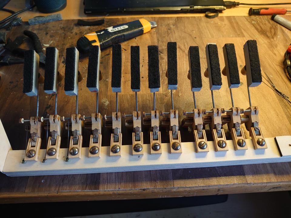
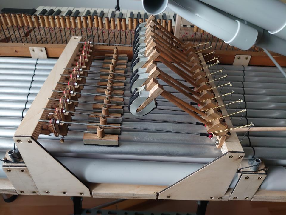
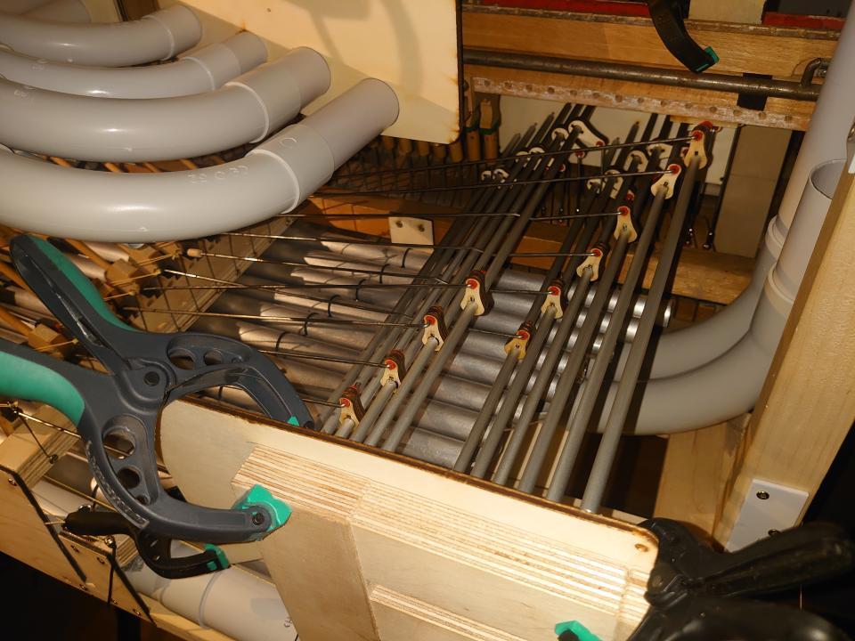
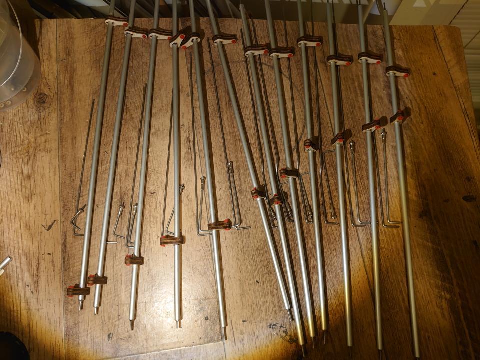
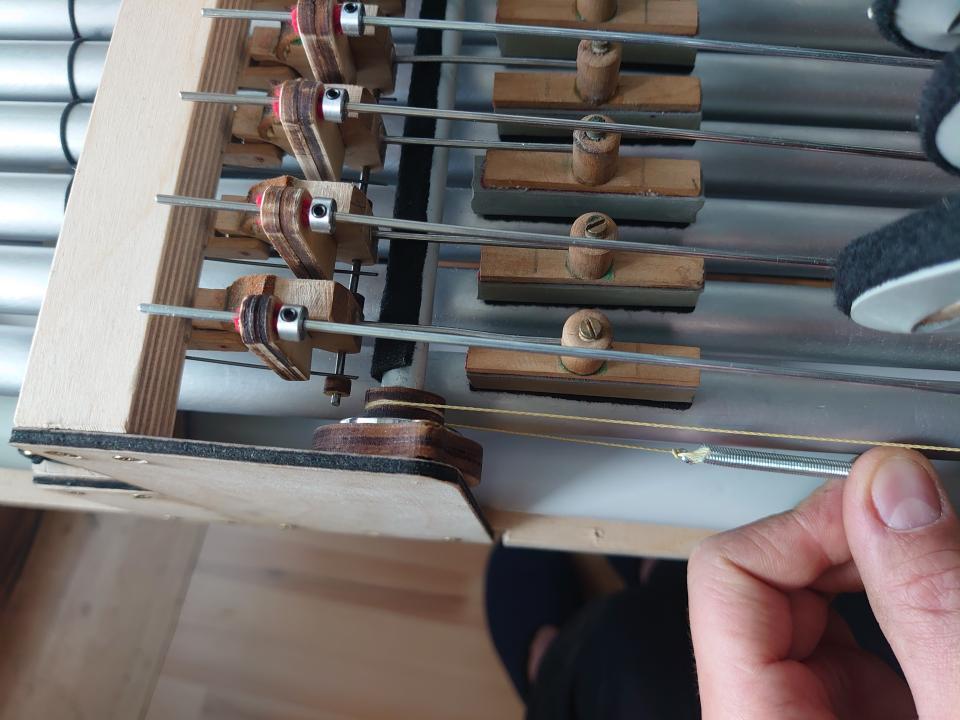
Cut off the original hammer.Add a damper in its place.Dampers also need a spring so they can press against the note and mute it.I also prepared springs for the hammers.And bent them according to the template.To connect the hammer and the string, I used kevlar thread. I also made them according to a template I had prepared in advance.On the other end, I attached the thread to the hammer using a steel pin.This is how the hammer assembly was gradually put together.The hammers strike the notes from above, and the spring returns them. Next, I needed to determine the position of the dampers relative to the hammers.Then I assembled everything as a test and tried it out.When I was satisfied with the result, I made holders and installed them in the instrument.Then I could screw the dampers onto the holder one by one.Completed damper assembly.The next step was figuring out how to activate the dampers. They lift with the movement of the hammers, so I connected them with wire. I used felt on all pins and joints to keep the mechanism silent.(Almost) completed assembly of dampers and hammers.
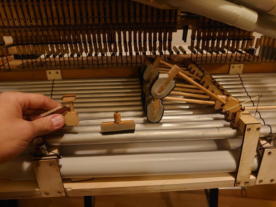
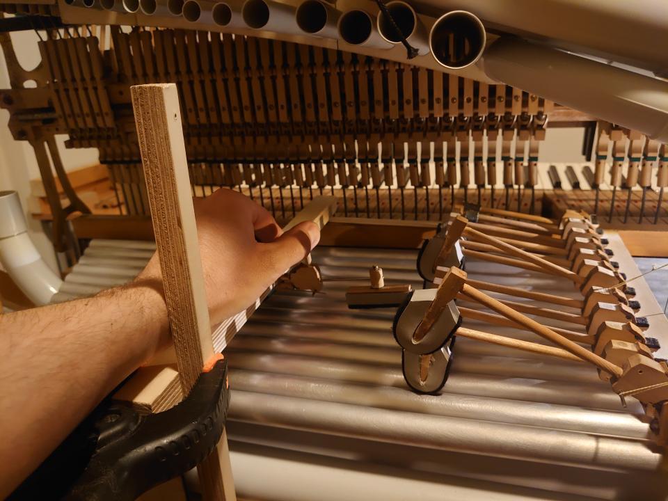
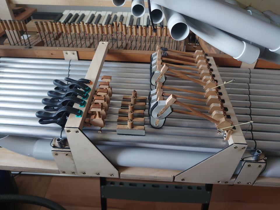
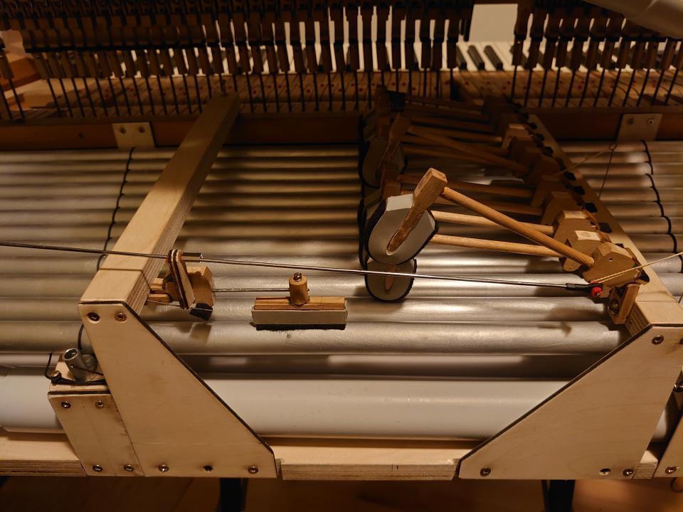
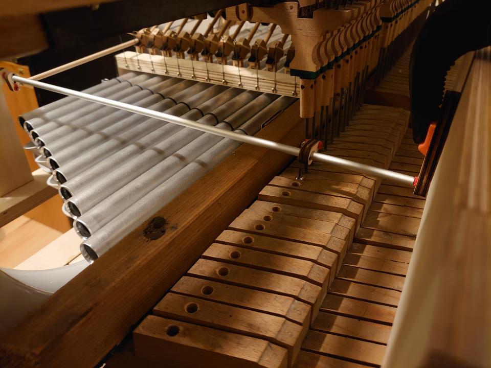
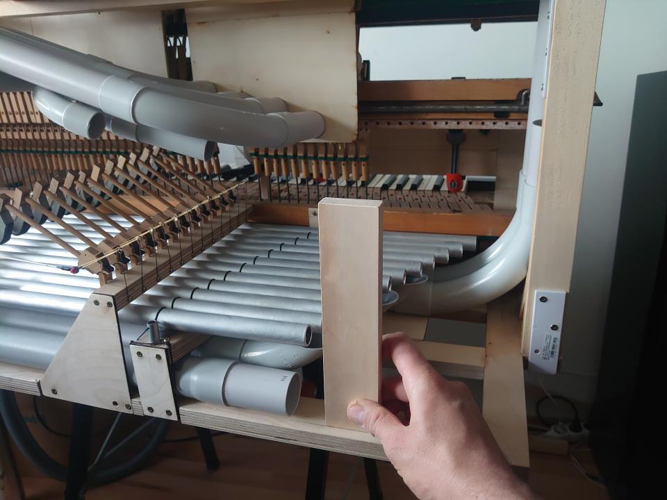
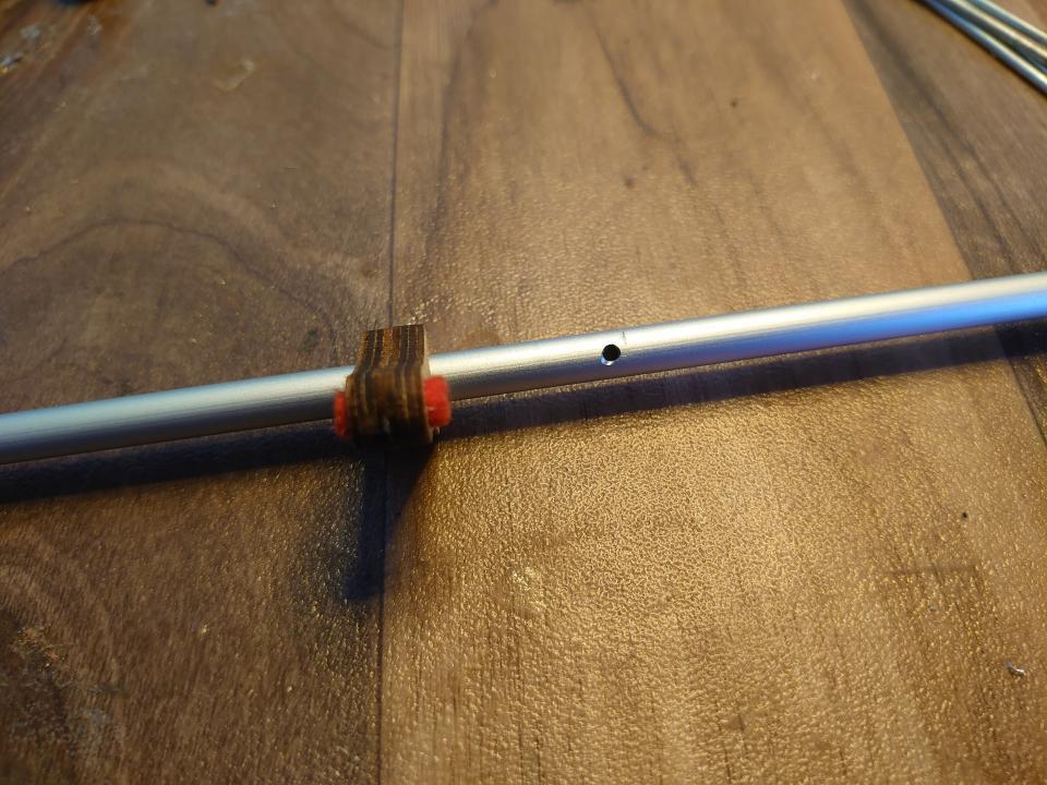
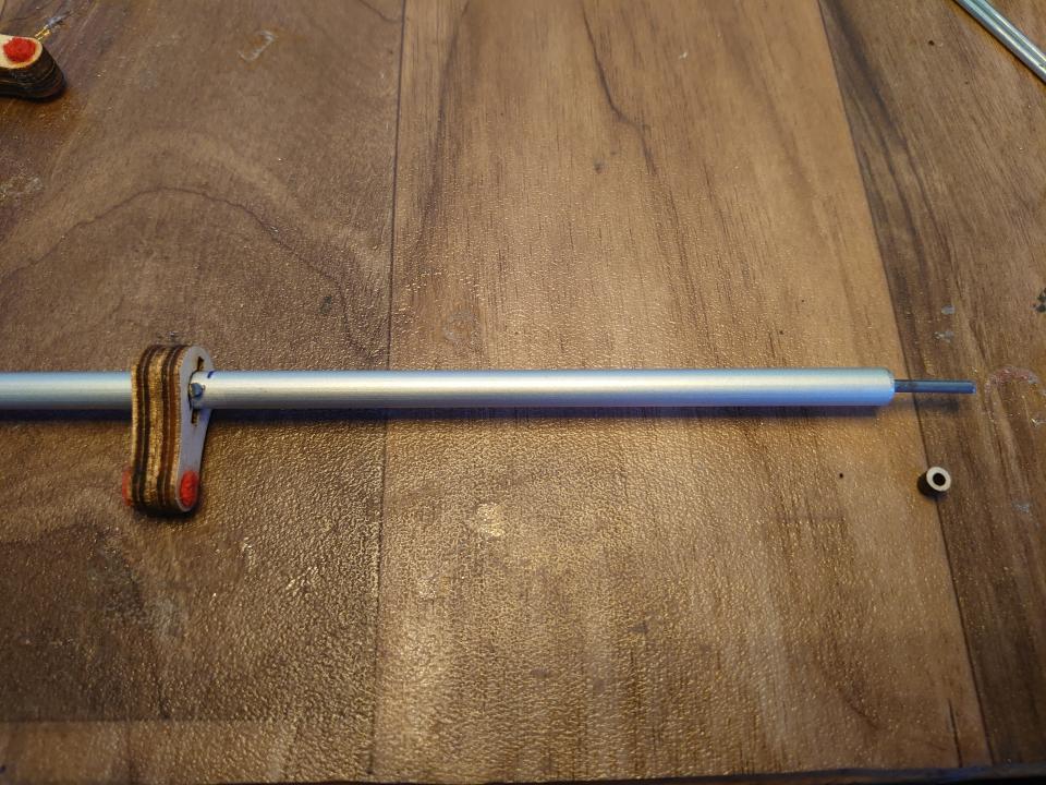
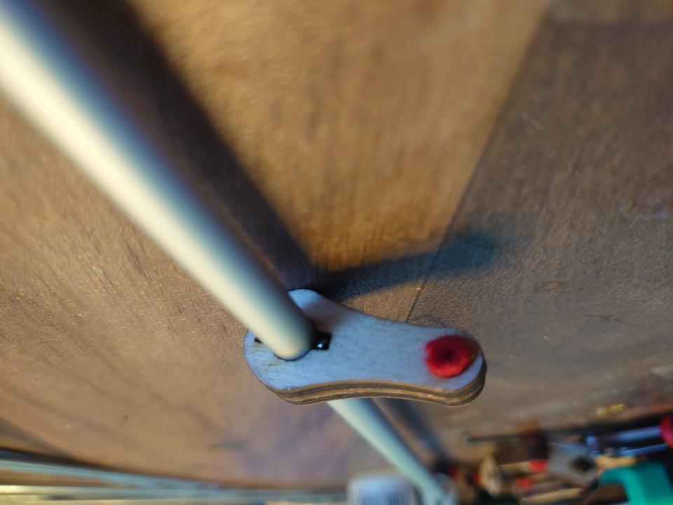
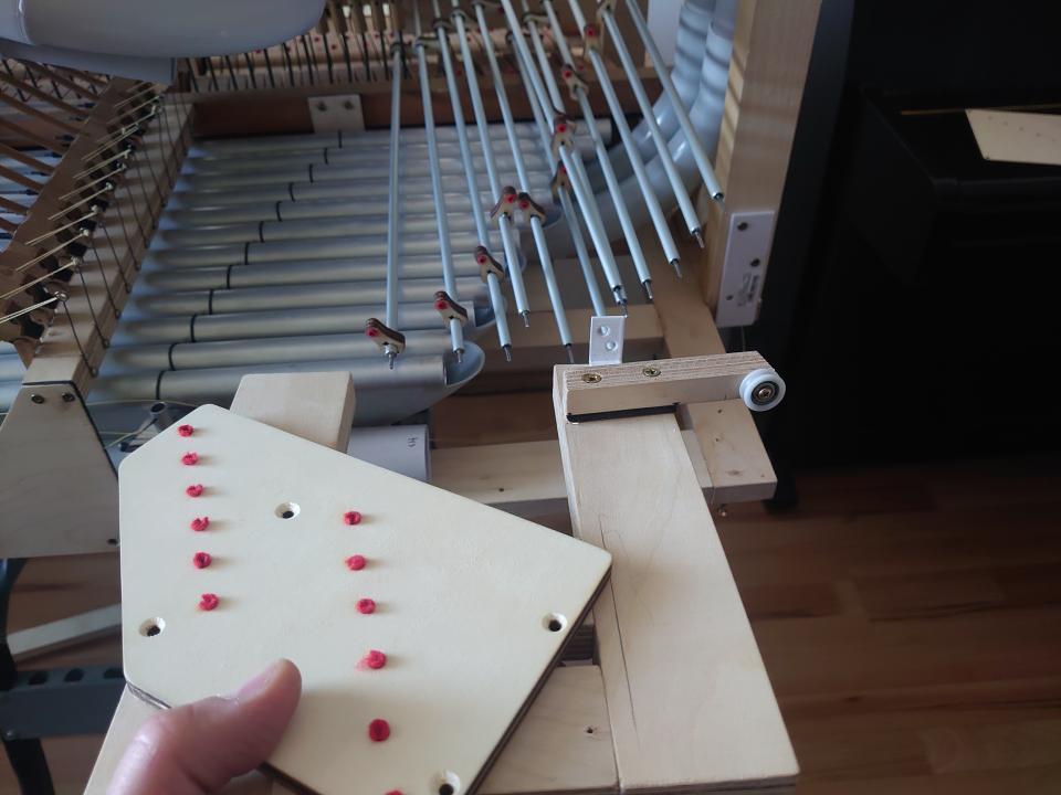
With this step, the mechanism was ready; all that remained was to connect the hammers to the keys. For this, I used a so-called mechanical action (also used in organs). The vertical movement of the key is converted into a rotational motion, and at the other end of the shaft, it is converted back into vertical movement, but in a different direction.
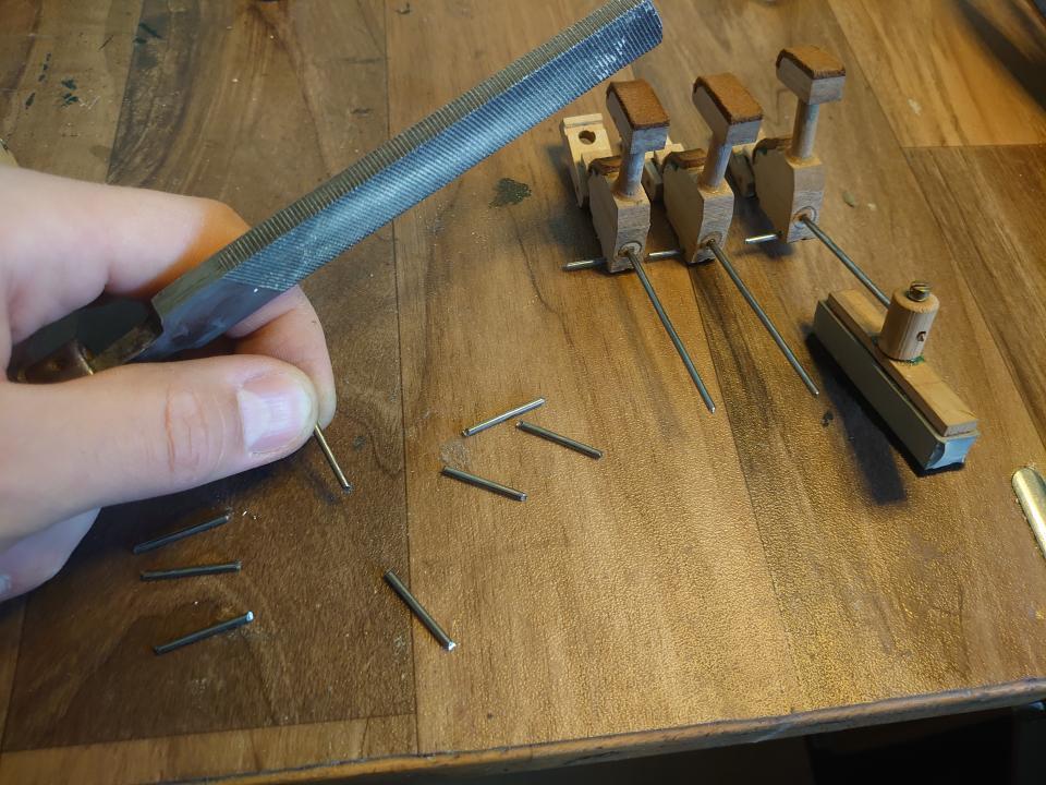
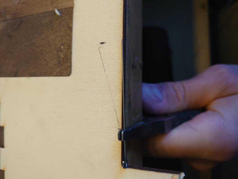
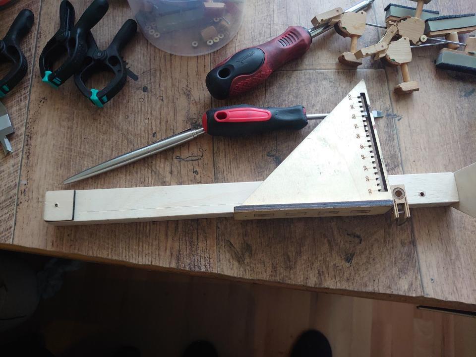
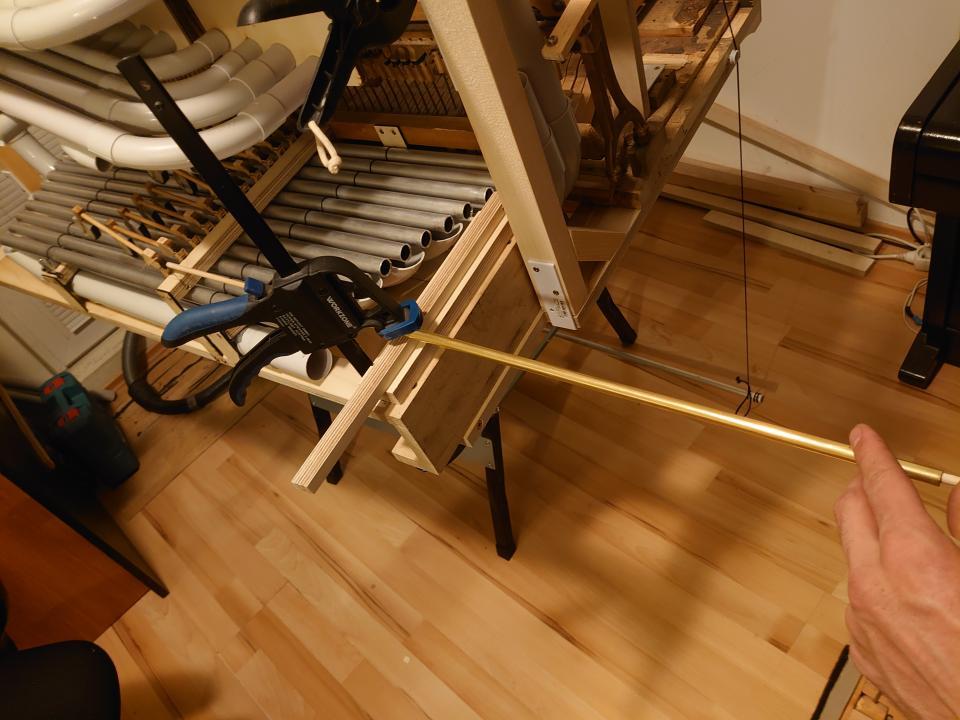
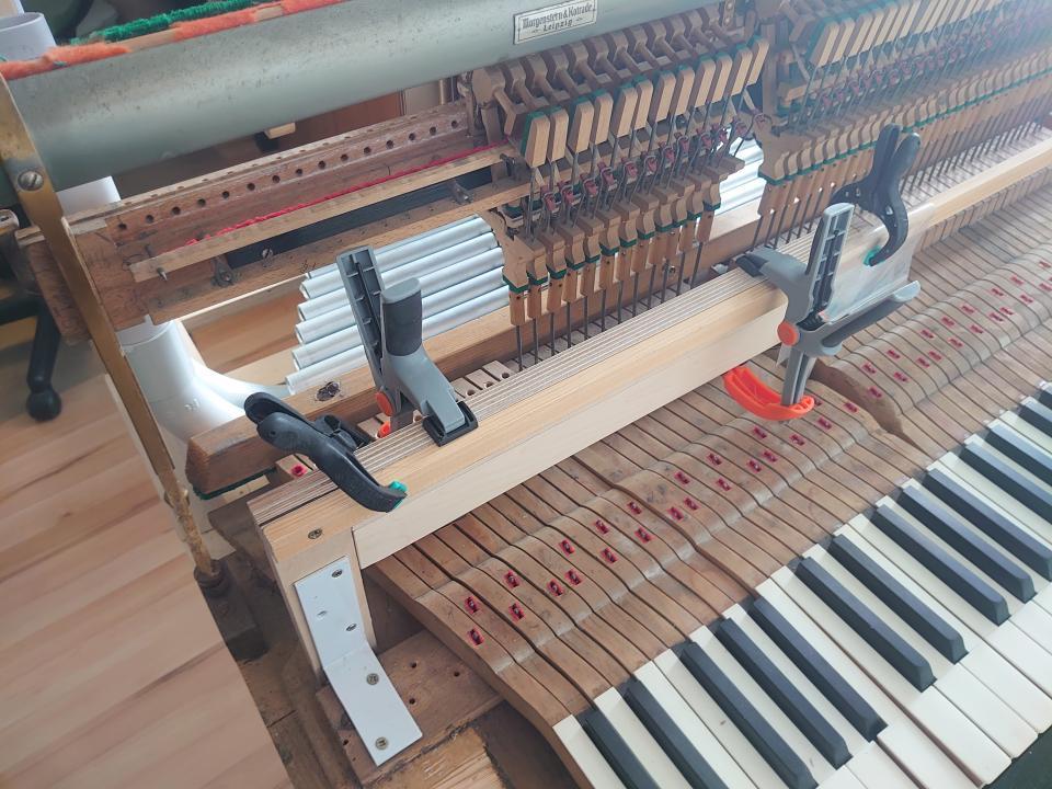
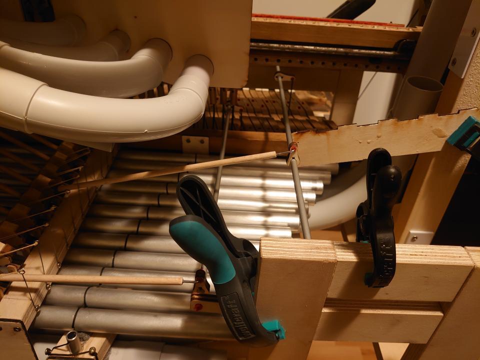
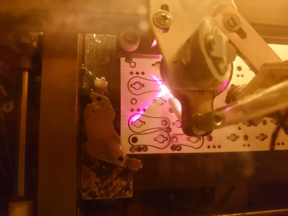
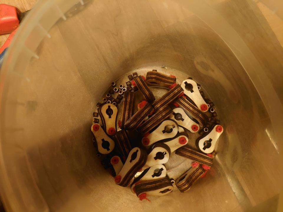
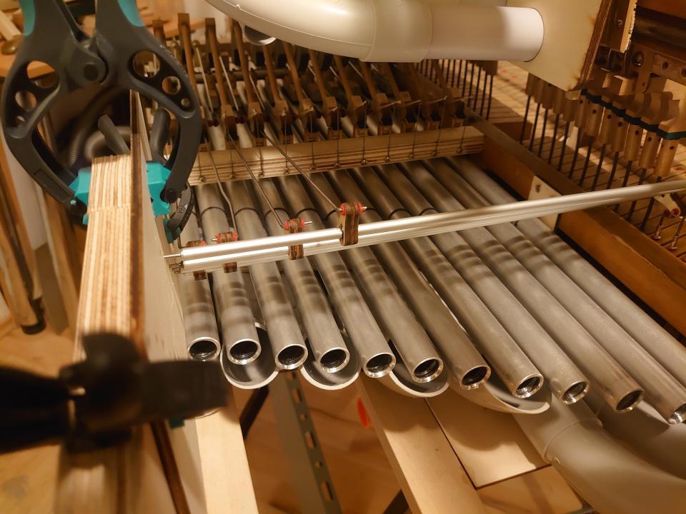
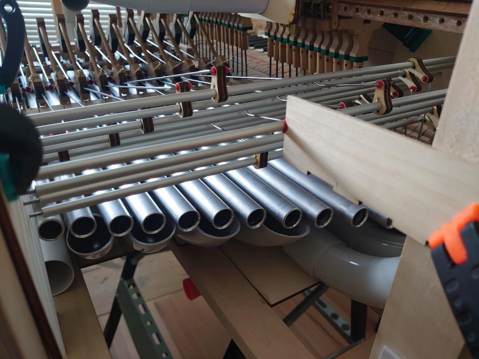
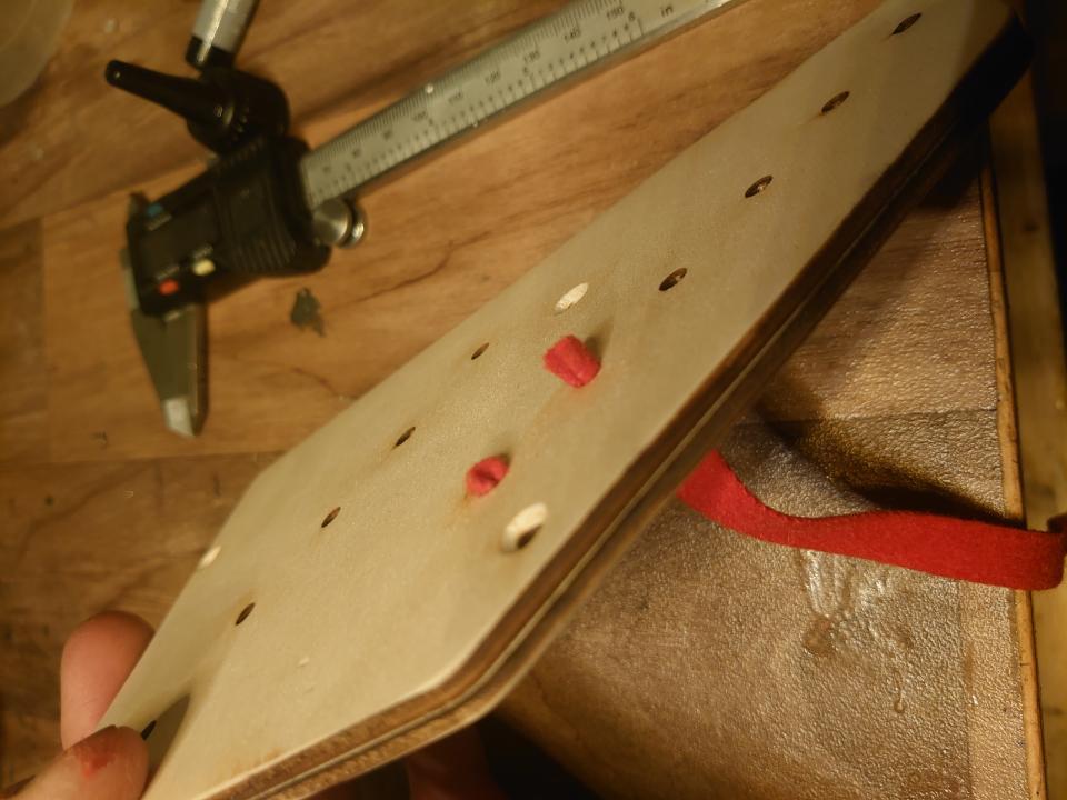
Test setup for hammer activation. The rod, which I press with my thumb, pushes the hammer. It must not push too hard, because if the hammer constantly touched the note, it would immediately mute it. Once I confirmed that it would work this way, I could start the actual work.First, I had to remove the original parts of the key mechanism.The wires sticking out of the keys were unnecessary.They were replaced by holes filled with felt.Then, make a test tracker action for a single note.The video shows the operation of the tracker action.Tracker action holder.And the second one from the back.I assembled everything temporarily using clamps. Here you can also see the rod that activates the hammer. The left tracker action shaft (for the B note) already passes between the keys of the next octave—there wasn’t much space to spare.I designed and made the parts for the mechanism myself using a laser. I determined the length of the levers based on the original mechanism.Of course, each one must have a felt lining.Preparing the ends of the shafts.Gluing the ends into the shafts.Hole for the lever’s securing pin.Installing the lever on the shaft. Each lever has a precisely defined position and angle, which I had to measure in advance.The pin prevents the lever from rotating on the shaft.Installing the shafts into the instrument.While assembling, I also had to make sure that the individual parts of the mechanism didn’t interfere with each other.Temporarily assembled tracker action.Then I could disassemble it entirely. Each key is connected to the lever by a linkage made from a bicycle spoke. I used these because they have a thread and a nut, allowing me to adjust the lift for each key individually.After disassembling, I made the final board with holes. Of course, each hole had to be lined with felt.During testing, I found that the shafts were too soft to withstand the forces generated during playing without bending (a consequence of limited space). I solved this problem with an additional board placed in the middle of the shafts to support them.View of the tracker action from the keyboard.Shot showing how the hammer works together with the damper.
The last important element is the pedal mechanism. I implemented it with a rotating shaft mounted beneath the dampers.
Installing the bearing holder for the shaft.The shaft is controlled by a kevlar cord, which returns to its original position with a string.Prepared pedal from the original piano.The video shows how the pedal mechanism works. It is divided into two parts: the bass section and the remaining four octaves.
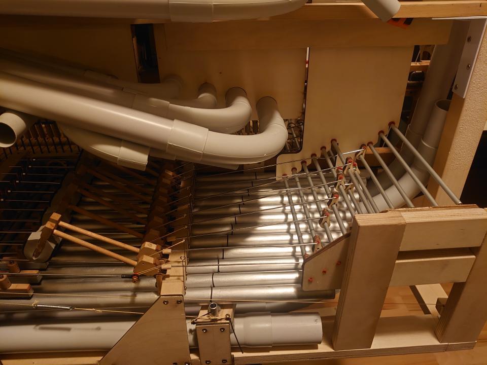
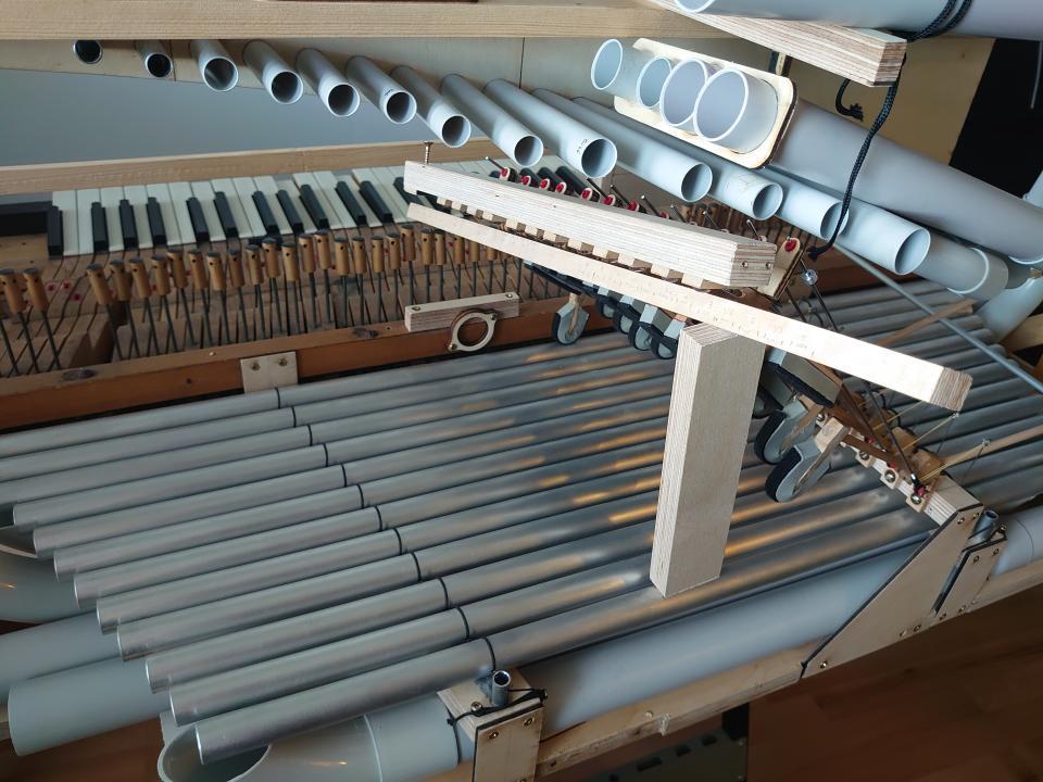
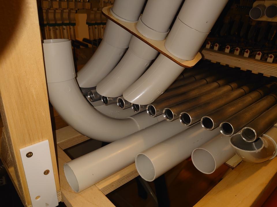
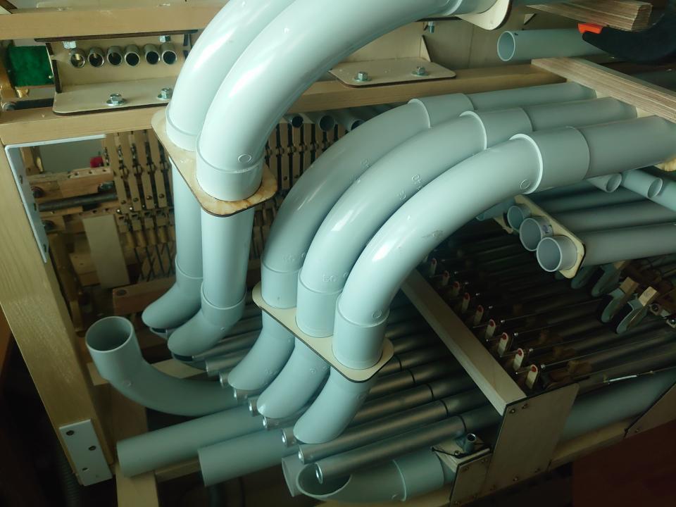
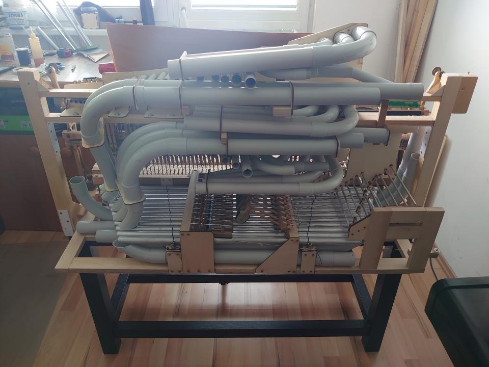
After completing all the mechanisms, I could add the remaining resonators for the bass notes. Some resonators fit under the notes, but since they are larger than the notes, some had to be placed on top.
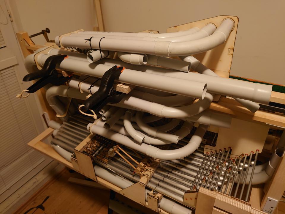
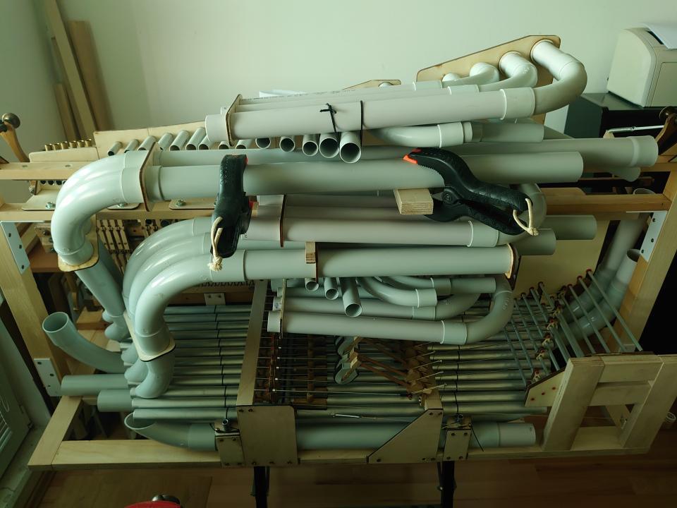
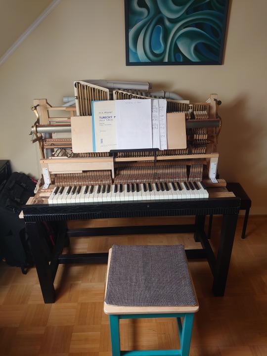
The finished instrument with its stand. The case for the instrument will be made at a later date.View of the instrument from the back.
Assembling the instrument was not the end of the work. What followed was endless fine-tuning of the mechanism so that the individual tones would be as balanced as possible and the instrument would be comfortable to play.
We use cookies on our website to give you the most relevant experience by remembering your preferences and repeat visits. By clicking “Accept All”, you consent to the use of ALL the cookies. However, you may visit "Cookie Settings" to provide a controlled consent.
This website uses cookies to improve your experience while you navigate through the website. Out of these, the cookies that are categorized as necessary are stored on your browser as they are essential for the working of basic functionalities of the website. We also use third-party cookies that help us analyze and understand how you use this website. These cookies will be stored in your browser only with your consent. You also have the option to opt-out of these cookies. But opting out of some of these cookies may affect your browsing experience.
Necessary cookies are absolutely essential for the website to function properly. This category only includes cookies that ensures basic functionalities and security features of the website. These cookies do not store any personal information.
Any cookies that may not be particularly necessary for the website to function and is used specifically to collect user personal data via analytics, ads, other embedded contents are termed as non-necessary cookies. It is mandatory to procure user consent prior to running these cookies on your website.